|  |
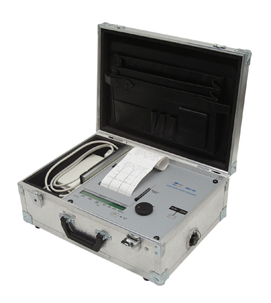
MD120 B WIRE ROPE DEFECTOGRAPH
The Instrument Set for Non-destructive Magnetic Testing of Wire Ropes
 Since
1979, Meraster has supplied instruments to estimate the in-situ deterioration
of wire ropes around the world.
Since
1979, Meraster has supplied instruments to estimate the in-situ deterioration
of wire ropes around the world.
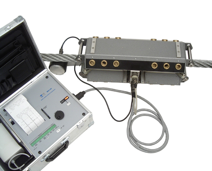
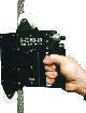
The operation of our NDT instruments is based on permanent magnet method, which was developed in Poland and is used throughout the world. Meraster's standard range of sensing measuring heads can be used for ropes ranging from 8 to 90 mm diameter. Custom designed heads are also available. For smaller ropes our MD-20 hand-held head-tester can be used.
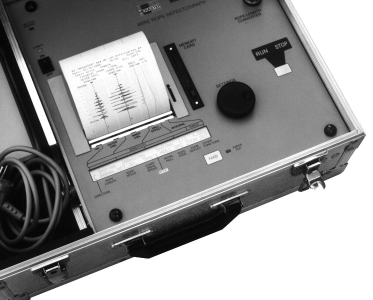
Recently developed by Meraster, the MD120 recording system includes a specially designed portable chart recorder with additional data recording which can be transferred to a computer. This unique instrument has been designed as a helpful and comfortable tool, to meet the special needs of rope experts in industrial environments.
Unique features:
- Detecting the position of defects throughout the rope's entire length and depth
- Using mathematical integral method for easier readout of high density defects
- Zoom replay of recorded defects
- Diagram solid state memory
- Computer interface
- "Settings with rope code" memory
:
SPECIFICATIONS OF MD120 B DEFECTOGRAPH
AND ITS MEASURING HEADS
Rope size range
| GP series standard heads diameter | from 8 to 85 mm |
| heads GP-1 type | from 30 to 85 mm |
| heads GP-2 type | from 20 to 60 mm |
| heads GP-3 type | from 10 to 30 mm |
| head GP-4 | from 10 to 26 mm |
| head GP-5 | from 10 to 15 mm |
| heads GP-6 type | from 8 to 14 mm |
| Hand-held tester MD-20 as a head | from 8 to 22 mm |
| GM series light-weight heads | from 10 to 90 mm |
Rope types
wire ropes made of ferromagnetic steel, any form of construction
Detected rope defects
- defects characterised by stepwise changes in rope cross-section, i.e. broken wires, pitting corrosion, etc., are detected using inductive sensors in all heads
- larger losses in a rope's metallic cross-section, i.e. wear, corrosion in longer length etc. are detected using additional Hall-effect sensor in GP-1(h), GP-2(h),
- real distortion
GP-3(h) and GM series heads
all important defects to estimate rope deterioration; maximum sensitivity may be as high as 0.05% of nominal rope metallic cross-sectional area (but such defect readability depends on the rope's construction)
Defect positioning on rope length
with rope length converter RI, mounted in heads GP-1 type, GP-2 type,
GP-3 type, GM or separate for others
Defect positioning of depth inside rope
with heads equipped with double inductive sensors ("inner" and "outer"),
i.e. heads GP-1 type, GP-2 type, GM
Operating conditions
| Temperature | from -25° to + 40° C |
| for recording on paper | from 0° to + 40° C |
| Relative humidity | to 95% |
| for recording on paper | from 25 to 85% |
Dimensions and weight of measuring heads
See: "GP Measuring Heads", "GM
Measuring Heads", "MD-20 Wire Rope Tester"
- SIGNAL RECORDER.
Application range
This instrument is intended to record signals from magnetic sensing
heads for testing wire ropes. It may also be direct applied to recording
other electric signals within its sensitivity range 1mV/mm to 3.2 V/full
scale or it may be customised to record within another required range,
from 50 µV/mm.
Main modes
- chart feed at constant selectable speed
- chart feed synchronous to rope movement
- 4 measurement channels -
- 2 channels of inductive sensors (coils) signals,
- 1 channel of Hall-effect sensor signal,
- 1 channel of mathematical integration of the inductive signal,
- rope length printout in meters by 5 cm of chart,
- time marks every 1 second and 10 seconds
- printout of recorder settings, rope code settings, time and date
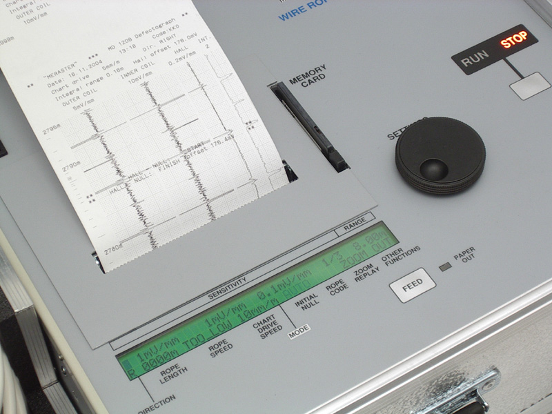
Example
Wire rope test chart
Recording method
Thermal array line printing head, printing on thermal paper on a roll
112 mm x 25m
- resolution 8 dots/mm
- channel format - overall width 103 mm
- Induction channels ± 18 mm each
- Hall channel ± 9 mm
- Integral channel 9 mm
- grid every 1mm and 10 mm in separate channels
0.05 to 10 m/s
Displayed rope speed range
0.05 to 9.99 m/s by 0.01m/s, over range indicated
Rope length display range 1 to 9999 m by 1 m reversible, up/down counting option, initial length setting capability
Length converter input
2 x 100 pulses/m (type RI)
Paper chart drive
1, 2, 5, 10 mm/m of rope or 1, 2, 5, 10 mm/second at synchro-feed rope
speed should be limited
| at 1 mm/m to 7.0m/s |
| at 2 mm/m to 7.0m/s |
| at 5 mm/m to 3.6m/s |
| at 10 mm/m to 1.8m/s |
"Zoom replay" memory capacity 18.75 m of rope or 18.75 seconds of recording
Acoustic signal of rope defect level
10, 20,....to 90% of full scale of the inner sensor channel (beeper
and also headphones)
"Settings & Rope Code" Memory
Capacity 100 items
Indicators
- liquid crystal display 2 x 40 characters
- RUN or STOP
- LED indicator POWER ON
- LED indicator PAPER OUT
- multicolour LED indicator of battery charging
| Type: | SRAM Memory Card | 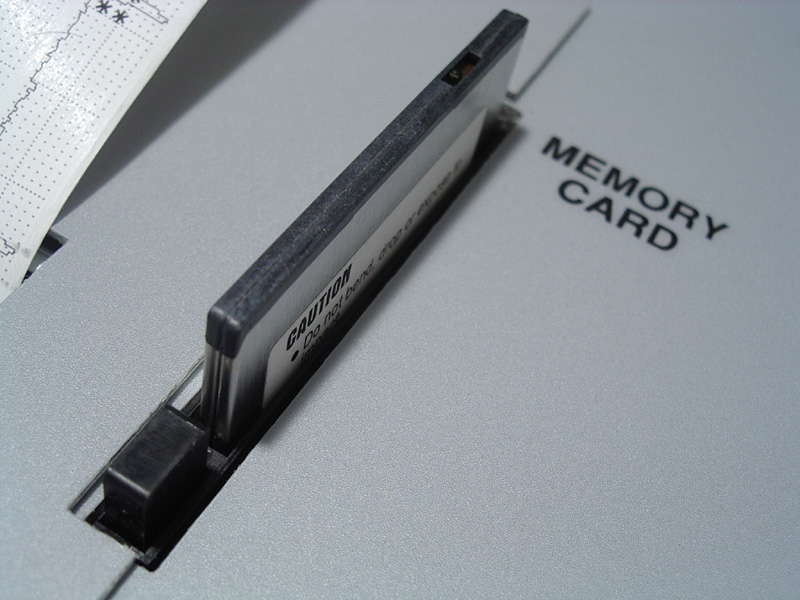 |
| PCMCIA type I or II, | ||
| Capacity: | 512 kB to 4 MB, i.e. | |
| 300 to 2400 m of rope at synchro mode | ||
| or 300 to 2400 seconds (40 min) of recording | ||
| Recorded data: | 3 signal channels + integral channel | |
| at sampling rate 2.5 mm or ms | ||
| recorder settings, rope code, time, date | ||
| rope length counter | ||
| Data replaying: | printing selected sectors with MD120 | |
| with computer and software tools |
Required interface for data transfer from diagram memory to the computerPCMCIA port & professional, byte level software driver
Sensitivity range
Outer and inner coil channels
- sensitivity at constant chart feed in mm/s and at synchro mode (mm/m), for rope speed 1m/s: 1, 2, 5, 10, 20, 50, 100, 200 mV/mm , at input resistance 21.5 kohm
- actual sensitivity at synchro mode
- for rope speed 0.05 to 10m/s depends on: "nominal sensitivity" x "value of rope speed in m/s"
- at speed less than 0.05 m/s: as for 0.05 m/s (max. sensitivity 1 mV/mm x 0.05 = 0.05 mV/mm)
- 0.1, 0.2, 0.5, 1, 2, 5, 10, 20 mV/mm
- differential input voltage
with DC component cutting, 0-400 mV
- 4 sensitivity levels
- running integral range 0.1 to 9.99 m or s
- AC Mains 220 V, 80 VA; other AC Mains voltages on request
- DC 12 V, 50 W
- Internal rechargeable battery for 4-6 hours of operation without external power
- deep discharge protection
- recharging while external power is connected
47.5 x 37 x 17.5 cm
Weight
with standard accessories 13 kg
Zawada
NDT
![]()
Language
versions
English Main
Page

MD120 Wire Rope Defectograph:

PC Card,
Optional Hardware and Software for PC

E-mail:
zawada@z-ndt.com
Fax:
++48 32 376 7900
Phone:
++48 32 271 6231
Mail:
Zawada NDT
ul. Tatarkiewicza 8
PL- 41-819 Zabrze
POLAND
Office/Visit:
ul. Roosevelta 120 B-5
(GPS: Roosevelta 118)
41-800 Zabrze